
When you are building multi-cylinder equipment you hear the same line again and again: “roughly in sync is good enough”. On a precision machine tool, a lifting platform or heavy equipment, “roughly” is the word that does the damage — one end of the machine lifts early, the workpiece is clamped out of shape, and in the worst case the whole machine is wrenched out of line. Synchronization accuracy is not a vague feeling; it is a hard figure that can be written on a drawing and calculated.
There are well-documented cases to prove it. A twin-platform multi-cylinder synchronization project at an aviation research institute required a displacement accuracy of 1–2 mm per platform and less than 1 mm of synchronization error between the two platforms. At that order of magnitude, “dividing the flow evenly” cannot possibly deliver — a complete system solution is the only way. This article takes the details apart layer by layer: where the error really comes from, what each kind of scheme does to cancel it, and how to calculate and choose in engineering practice.
1. Where synchronization error comes from: settling the account first
Out of sync simply means that at the same instant the cylinders do not have the same displacement (or the same speed). In an open-loop scheme that deviation accumulates the whole way and can never be corrected retrospectively; in a closed-loop scheme it is measured in real time and pushed back. The error has five main sources, and their weight is far from negligible:
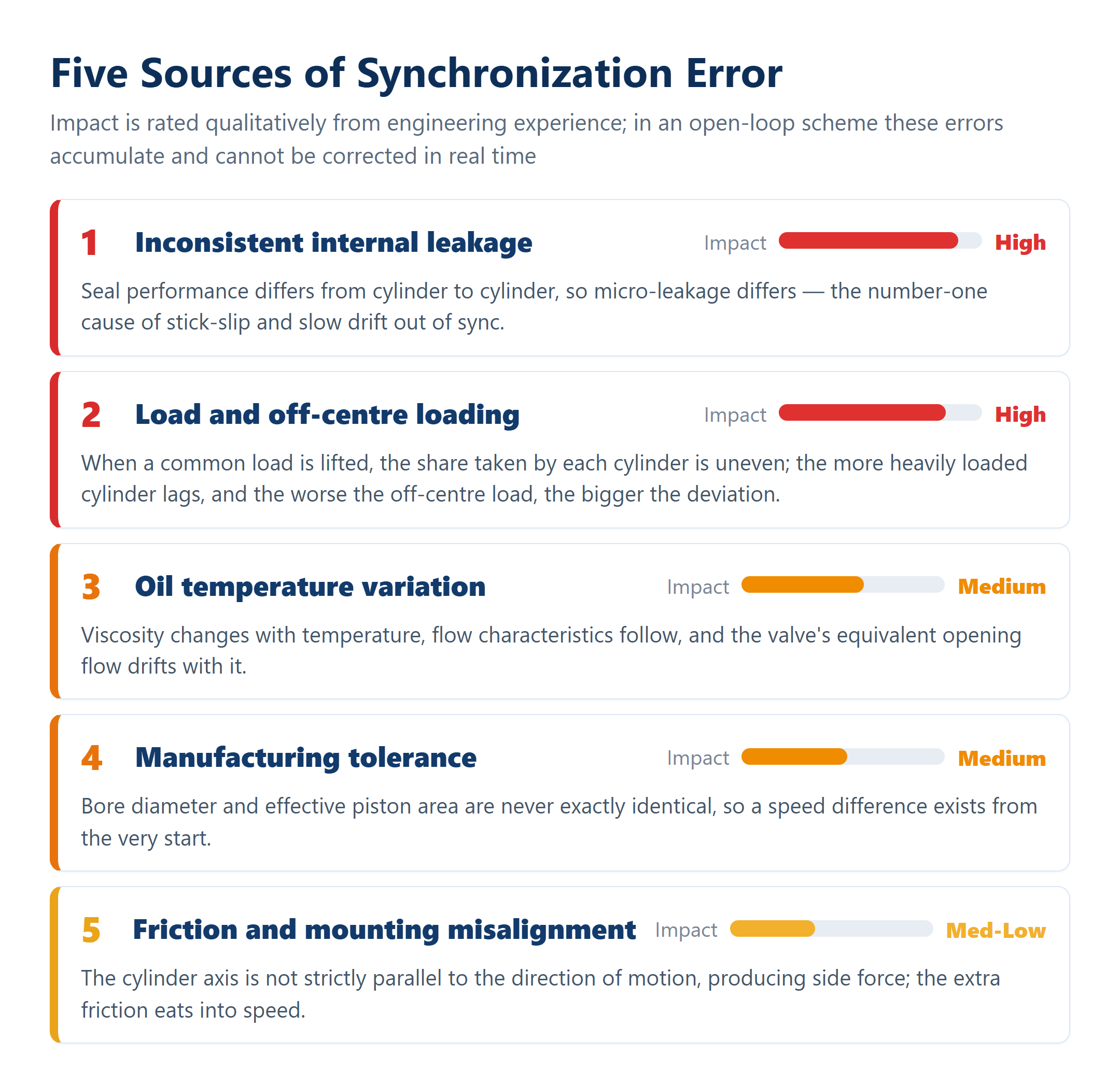
- Inconsistent internal leakage: seal performance differs between cylinders, so micro-leakage differs — the number-one cause of stick-slip and of slowly drifting out of sync.
- Load and off-centre loading: when a common load is lifted the forces are not shared evenly, and the more heavily loaded cylinder lags; the worse the off-centre load, the bigger the difference.
- Oil temperature variation: change the oil temperature and the viscosity changes with it, the flow characteristics follow, and the equivalent opening flow of the valve drifts too.
- Manufacturing tolerance: bore diameter and effective piston area are never one hundred per cent identical, so a speed difference exists from the very root.
- Friction and mounting misalignment: if a cylinder axis is not strictly parallel to the direction of motion, side force appears and the extra friction eats into speed.
Key insight: open-loop schemes (throttle valve, speed-control valve, flow divider-combiner) can only reduce error by “dividing more evenly” and cannot correct it while the machine runs; a closed loop cancels the error in real time by “measuring accurately and correcting fast”. That is the watershed between the accuracy of the two families of scheme.
2. Valve-controlled synchronization in detail: the flow divider-combiner valve
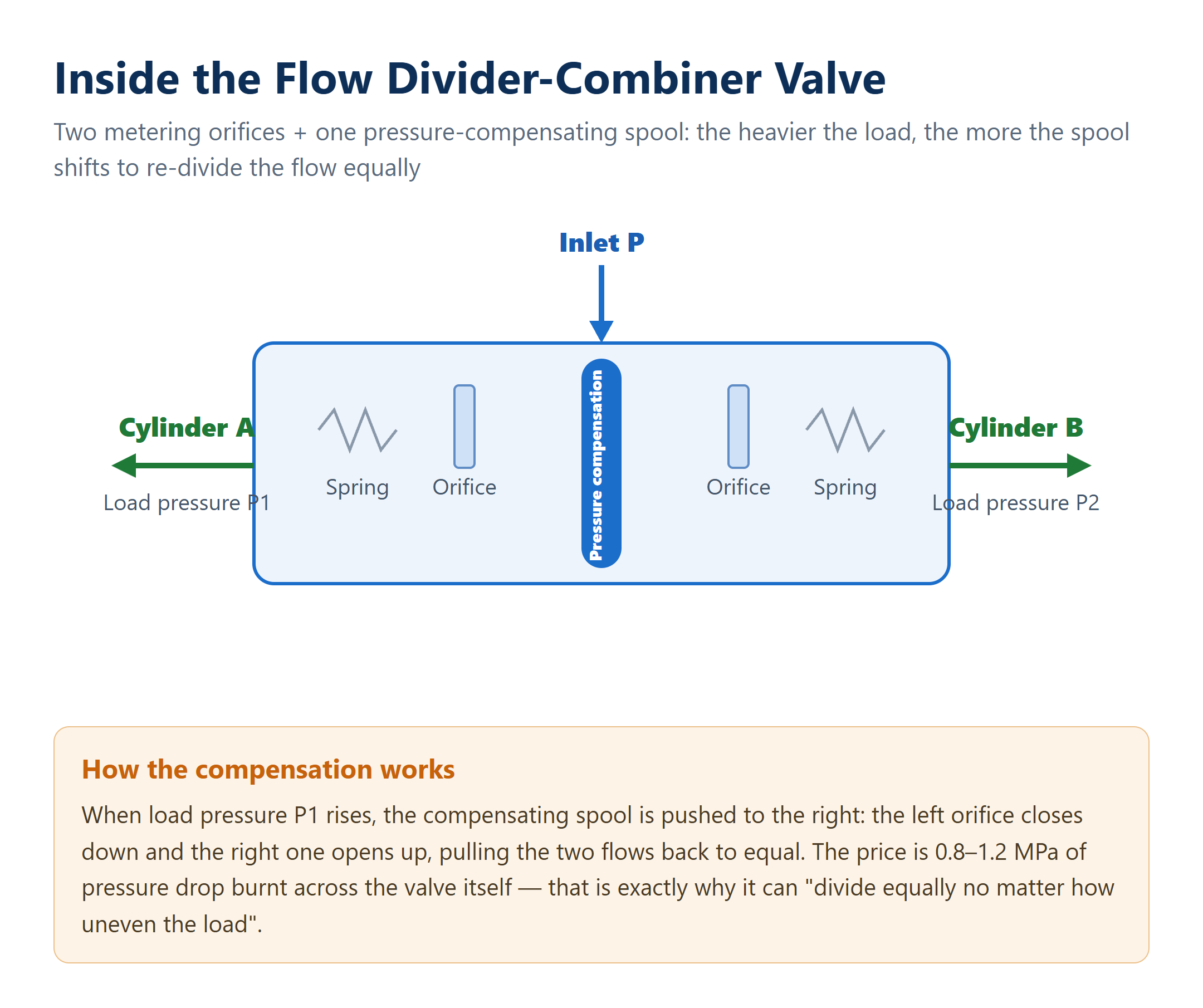
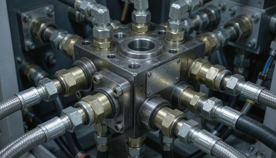
The most widely used synchronization device on the factory floor — the best value for money and needing no electrics at all — is the flow divider-combiner valve (synchronizing valve). Inside it, two metering orifices are integrated into a single spool, and pressure compensation divides the flow automatically: when one branch takes a heavier load and its pressure rises, the spool moves by itself, closing down the orifice on that side and opening the other, forcing the two flows back to equal. However uneven the load, it still divides the flow.
But three engineering details decide whether it can actually be used well, and they are where beginners come unstuck most often. These are the three hard limits of a flow divider-combiner valve:
- Pressure-drop cost | the valve itself burns 0.8–1.2 MPa of pressure drop (high-accuracy types even more than 2 MPa). System pressure has to leave that margin for it, so a low-pressure system (below 5 MPa) should basically leave it alone.
- Flow window | below 30% of the rated flow the pressure drop falls with the square of the flow and the dividing accuracy collapses. Choose the nominal flow close to the actual demand — never pick one several times larger “for safety”.
- Long-stroke limitation | 2%–5% is the proportional accuracy. Over a 1.5 m stroke the mismatch can reach 30–75 mm, and there is no correction during the travel. For a precision job (under 2 mm) it simply cannot cope.
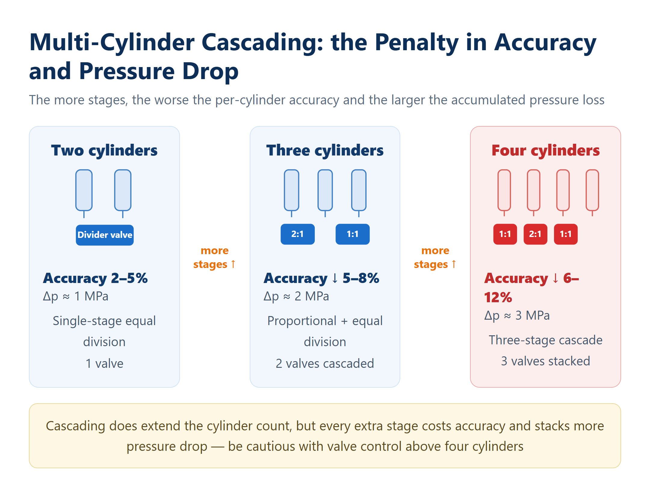
What about more cylinders? You cascade them. For example one 2:1 proportional divider valve plus one equal divider valve carries three cylinders; four cylinders take a three-stage cascade. The catch is obvious: the more stages there are, the worse the per-cylinder accuracy and the larger the accumulated pressure loss.
End-of-stroke compensation: at the end of the stroke many synchronizing valves bypass about 15% of the flow, “holding back” the cylinder that arrived first so the slower one can catch up, which reduces the accumulated error at the end. But it only looks after the end point, never the process.
3. The error-cancelling mechanism of volumetric synchronization: finishing with make-up oil
Synchronizing cylinders, synchronizing motors and series cylinders are a different family: they do not divide flow by throttling, they hold synchronization by geometrically equal displacement volumes. Leakage and manufacturing tolerance still accumulate, however, which is why every one of these circuits carries its own make-up and drain oil arrangement — designed specifically to deal with the accumulated error at the end of the stroke.
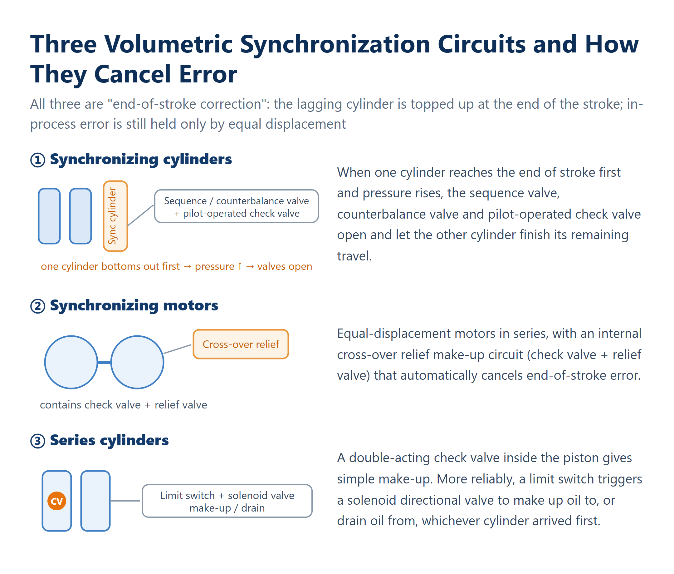
- Synchronizing cylinders: a make-up and drain circuit built from a sequence valve + counterbalance valve + pilot-operated check valve. When one cylinder reaches the end of its travel first and the pressure rises, those valves let the other cylinder complete its remaining stroke.
- Synchronizing motors: equal-displacement motors in series, with an internal cross-over relief make-up circuit (check valve + relief valve) that cancels end-position error automatically.
- Series cylinders: a double-acting check valve inside the piston gives simple make-up; more reliably, a limit switch triggers a solenoid directional valve that makes up oil to, or drains oil from, the cylinder that arrived first.
Be clear about the distinction: these are all “end-of-stroke correction”. They only wipe out the accumulated error at the end of the travel; error during the travel is still held back by equal displacement alone and is not corrected in process. Their accuracy therefore stays at 1%–5% and cannot reach millimetre level.
4. Closed-loop synchronization in detail: from measurement to correction
To press synchronization error down to ±1 mm, or even ±0.5 mm, you have to go to closed-loop electro-hydraulic control. In essence it is a real-time “eyes–hand–brain” loop in which every deviation is seen and corrected:
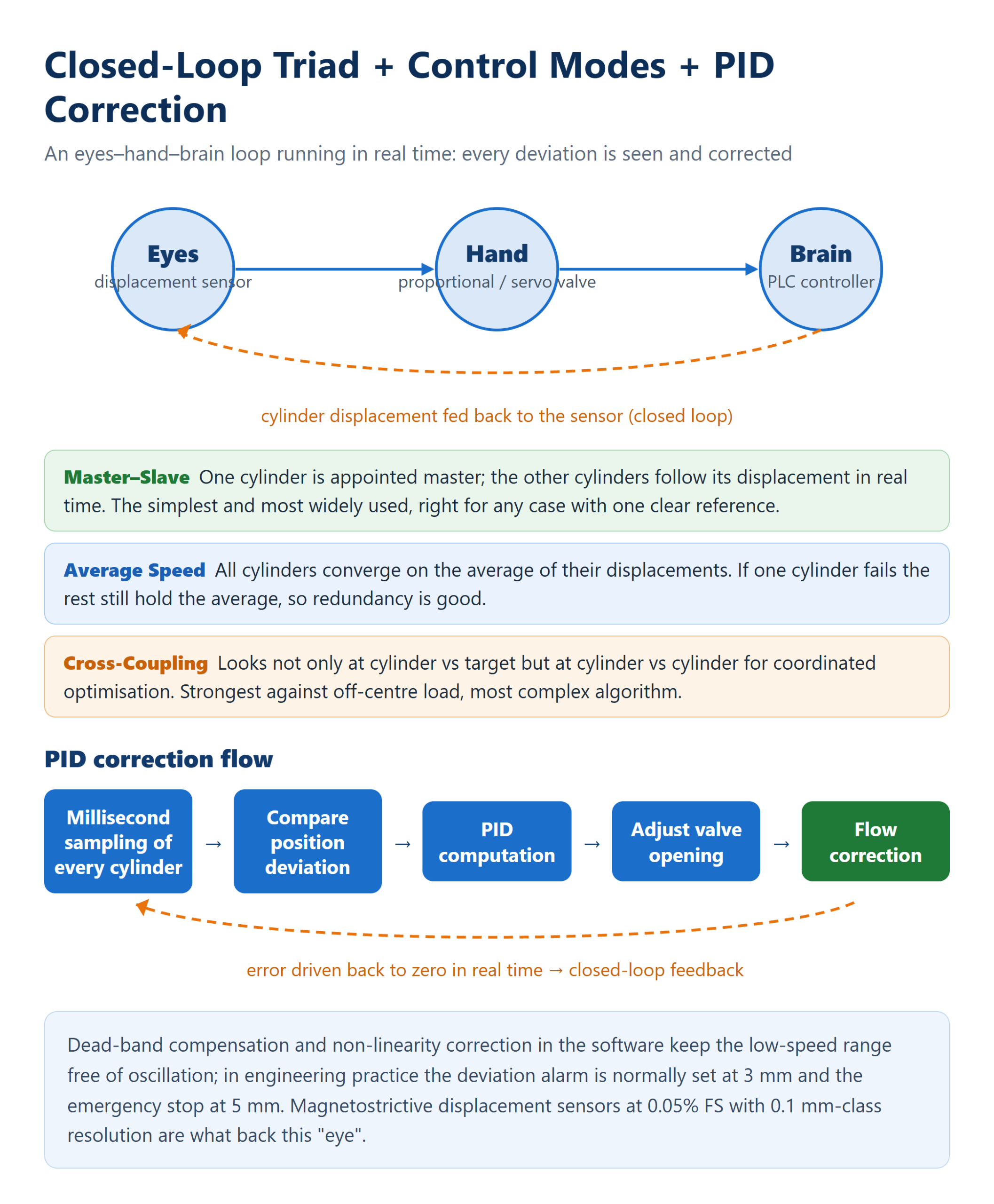
- Eyes: one high-precision displacement sensor per cylinder, usually a magnetostrictive sensor with 0.05% FS accuracy and 0.1 mm-class resolution.
- Hand: one high-response proportional directional valve per cylinder (with integrated amplifier), or a servo valve where faster dynamics are needed, to deliver the oil precisely.
- Brain: a PLC or motion controller (for example Siemens S7-1500T, Beckhoff) that runs the control algorithm and issues the commands.
Control mode is selected to suit the requirement, with resistance to off-centre loading increasing from one to the next. The three closed-loop control modes:
- Master–slave | one cylinder is appointed master and the others follow its displacement in real time. The simplest and most widely used, right for any case with one clear reference.
- Average speed | all cylinders converge on the average of their displacements. If one cylinder has a problem the rest still hold the average, so redundancy is good.
- Cross-coupling | it looks not only at cylinder versus target but at cylinder versus cylinder, optimising them jointly. The strongest against off-centre loading, and also the most complex algorithm.
How does PID swallow the error? The controller samples every cylinder position at high frequency in the millisecond range → the deviation is computed → the algorithm works out whether each cylinder’s valve should open more or less → the flow is corrected in real time. Together with dead-band compensation and non-linearity correction in the software, the low-speed range does not judder either. In practice the deviation alarm is normally set at 3 mm and the ultimate safety stop at 5 mm: the moment the tolerance is exceeded the machine stops, so the equipment cannot be wrecked.
In one sentence: open loop “divides evenly”, closed loop “measures accurately and corrects fast” — and the accuracy gap between the two is exactly this real-time closed loop.
5. Worked example: choosing the scheme for a four-cylinder lift platform
Take a common duty and let the numbers speak. A four-cylinder lift platform: 50 kN per cylinder, 1.5 m stroke, 100 mm bore (effective area about 7.85 cm², corresponding to a working pressure of about 6.4 MPa) and a lifting speed of 0.05 m/s. Work through the two candidate schemes and everything becomes clear.
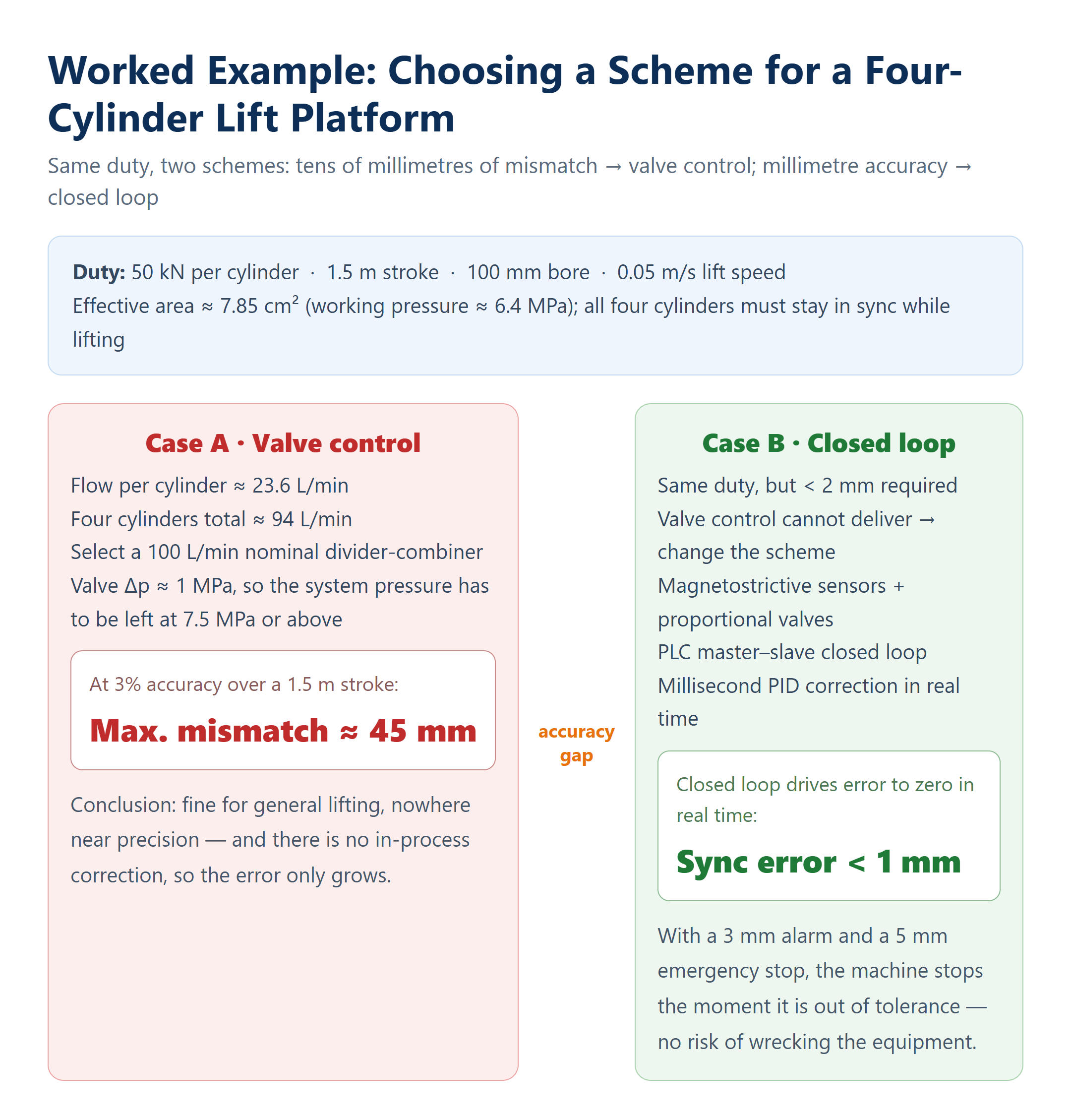
Same duty, two schemes:
- Case A · Valve control | flow per cylinder ≈ 23.6 L/min, four cylinders ≈ 94 L/min, so select a 100 L/min nominal divider valve; valve pressure drop about 1 MPa, leaving system pressure at 7.5 MPa or above. Taking the accuracy as 3%, over a 1.5 m stroke the maximum mismatch is ≈ 45 mm. Adequate for ordinary lifting, but not precision by any measure.
- Case B · Closed loop | on the same duty, if under 2 mm is required, valve control is helpless. Switch to magnetostrictive sensors + proportional valves + PLC master–slave control: millisecond-level PID presses the error below 1 mm, with a 3 mm alarm and a 5 mm stop.
The iron rule of selection: if tens of millimetres of mismatch are acceptable → use a flow divider-combiner valve, saving money and trouble; if millimetre level is required → a closed loop is mandatory. Do not force valve control into a precision job: that is gambling with equipment safety.
6. Commissioning and pitfalls: without the basics, even a closed loop is wasted
Precision synchronization is a system job, and the thing to fear most is piling advanced control on top of foundations that were never built properly. Every one of the details below has a direct bearing on whether the final accuracy target is met.
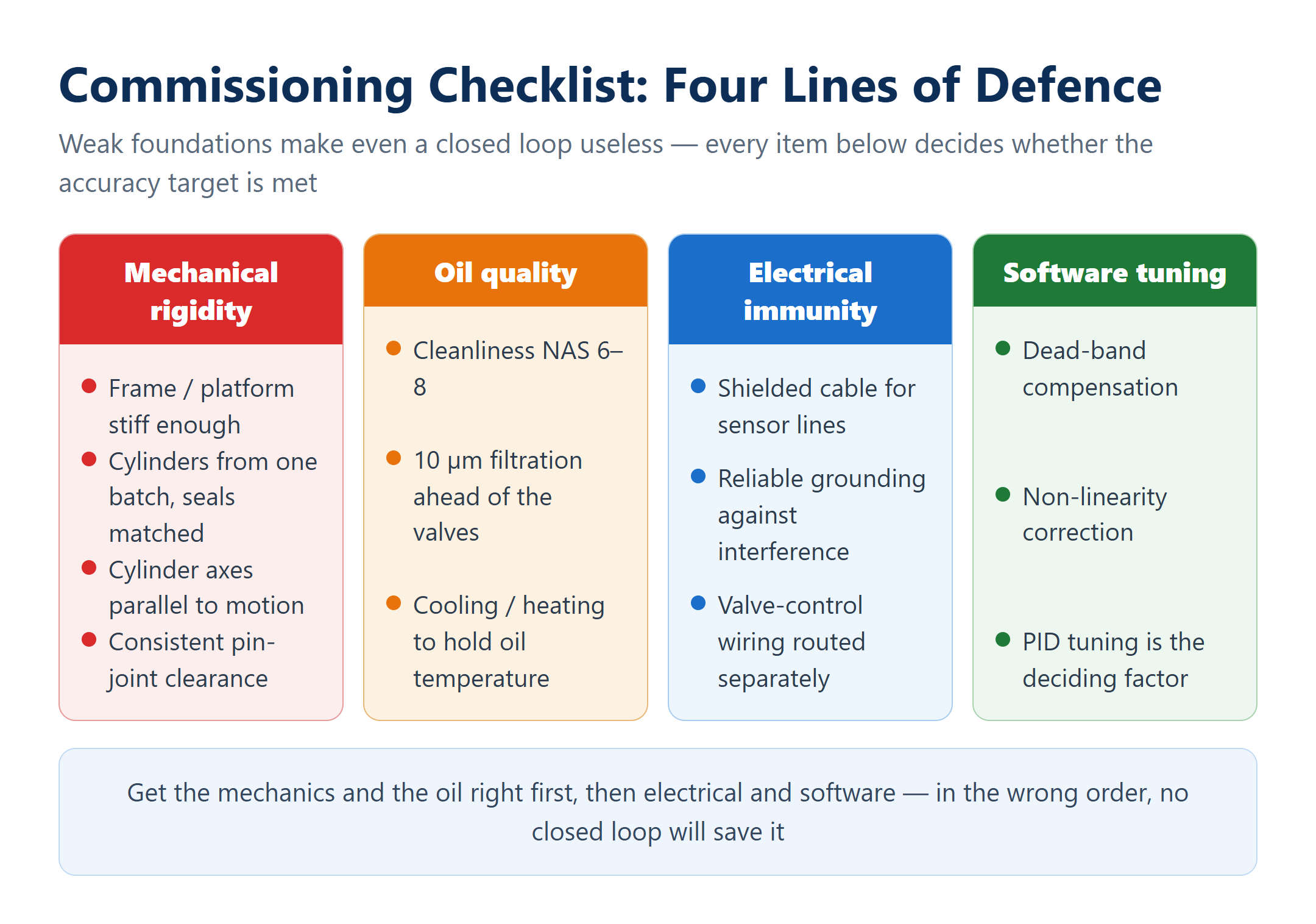
- Mechanical rigidity: the supporting frame or platform must be stiff enough, otherwise however well the cylinders synchronize the end effector still tilts.
- Cylinder consistency: prefer cylinders from the same production batch with matching seals (Stepseal, Glyd ring), so internal leakage is extremely small and similar from one cylinder to the next.
- Mounting accuracy: every cylinder axis strictly parallel to the direction of motion to prevent side loading; keep the pin-joint clearance identical.
- Oil quality: cleanliness NAS 6–8, with 10 µm filtration ahead of the valves; fit cooling and heating to hold the oil temperature steady.
- Electrical immunity: shielded cable and reliable grounding for the displacement sensor leads and the valve control wiring, to block electromagnetic interference.
- Software tuning: get the proportional valve dead band and non-linearity compensation right; PID parameter tuning is where the job succeeds or fails.

发表回复